Description
#Electrical Control Diagram #Reverse Osmosis System #High Pressure Pump Control #PLC Program #Siemens S7-1200 #Industrial Automation #Electrical Drawings
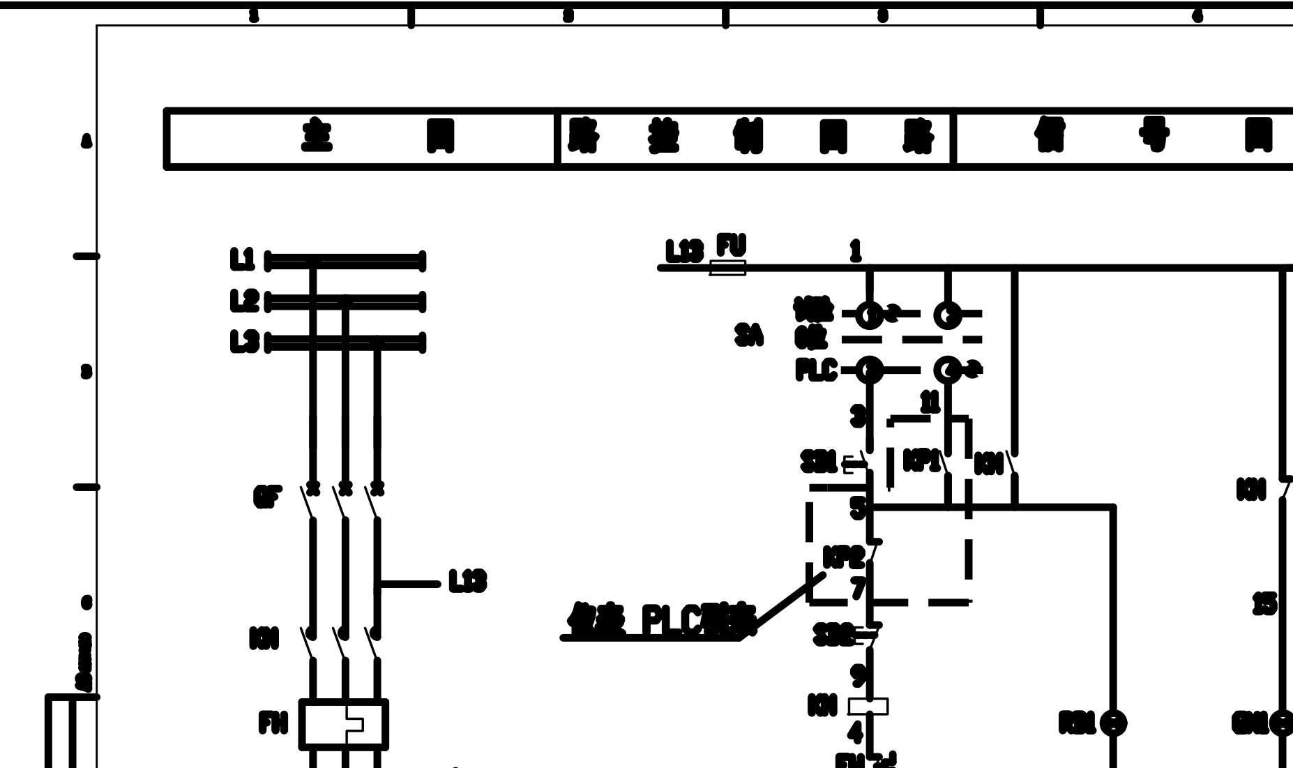
The 250 tons/hour reverse osmosis high pressure pump electrical control diagram is a set of electrical design documentation aimed at large reverse osmosis (RO) water treatment equipment, covering high pressure pump electrical control systems, PLC control circuits, and automation control schemes. The drawings include main circuits, control circuits, signal acquisition, safety protection, frequency control, and human-machine interaction, serving as technical reference materials for the design, installation wiring, equipment debugging, and maintenance of reverse osmosis equipment.
- PLC Automatic Control: Utilizes Siemens S7-1200 PLC control architecture to achieve automatic start-stop, interlocking control, and operational monitoring of the high pressure pump.
- Variable Frequency Constant Pressure Control: Combines frequency converters with PID control to achieve closed-loop pressure adjustment of the high pressure pump, meeting the constant pressure water supply requirements of the reverse osmosis system.
- Pressure Signal Acquisition: Supports real-time acquisition of system pressure data from pressure transmitters, providing feedback signals for automatic control.
- HMI Human-Machine Interface: Supports touchscreen monitoring of equipment operating status, parameter settings, fault alarms, and historical data viewing.
- Multiple Safety Protections: Integrates overload protection, phase loss protection, stall protection, grounding protection, emergency stop control, and equipment interlocking safety functions.
- Equipment Status Monitoring: Supports monitoring of motor vibration, bearing temperature, and key equipment operating status to enhance system reliability.
- UPS Control Power Supply: Configures a backup power supply scheme for the control system to enhance the continuous operation capability of the control system in case of power failure.
- Standardized Wiring Design: Includes design for power cables, control cables, signal cables, and terminal block numbering, facilitating construction installation and maintenance.
- Electrical Component List: Accompanies references for circuit breakers, contactors, relays, PLCs, frequency converters, and other major electrical components.
- Equipment Layout Diagram: Provides schematic layouts for control cabinets, high pressure pumps, motors, PLC cabinets, and on-site equipment installation.
- Process Interlocking Control: Includes three operating modes: automatic, manual, and maintenance, as well as automatic interlocking logic for low liquid level protection, pressure relief control, and membrane cleaning.
- Standard Legend Explanation: Accompanies complete electrical symbols, equipment codes, and terminal identification explanations, complying with industrial electrical design standards.
Software Features
- Complete Electrical Control Diagram: Provides complete electrical design documentation including main circuits, control circuits, protection circuits, auxiliary power, and signal acquisition.- PLC Automatic Control: Utilizes Siemens S7-1200 PLC control architecture to achieve automatic start-stop, interlocking control, and operational monitoring of the high pressure pump.
- Variable Frequency Constant Pressure Control: Combines frequency converters with PID control to achieve closed-loop pressure adjustment of the high pressure pump, meeting the constant pressure water supply requirements of the reverse osmosis system.
- Pressure Signal Acquisition: Supports real-time acquisition of system pressure data from pressure transmitters, providing feedback signals for automatic control.
- HMI Human-Machine Interface: Supports touchscreen monitoring of equipment operating status, parameter settings, fault alarms, and historical data viewing.
- Multiple Safety Protections: Integrates overload protection, phase loss protection, stall protection, grounding protection, emergency stop control, and equipment interlocking safety functions.
- Equipment Status Monitoring: Supports monitoring of motor vibration, bearing temperature, and key equipment operating status to enhance system reliability.
- UPS Control Power Supply: Configures a backup power supply scheme for the control system to enhance the continuous operation capability of the control system in case of power failure.
- Standardized Wiring Design: Includes design for power cables, control cables, signal cables, and terminal block numbering, facilitating construction installation and maintenance.
- Electrical Component List: Accompanies references for circuit breakers, contactors, relays, PLCs, frequency converters, and other major electrical components.
- Equipment Layout Diagram: Provides schematic layouts for control cabinets, high pressure pumps, motors, PLC cabinets, and on-site equipment installation.
- Process Interlocking Control: Includes three operating modes: automatic, manual, and maintenance, as well as automatic interlocking logic for low liquid level protection, pressure relief control, and membrane cleaning.
- Standard Legend Explanation: Accompanies complete electrical symbols, equipment codes, and terminal identification explanations, complying with industrial electrical design standards.